Assembling the Electronics
Now that the hardwood is finished, we can start assembling the electronics. We’ll need to insert the switches, design our circuit, and solder everything together. Luckily the circuitry is dead simple, so even beginners will have no trouble at all.
Inserting the Switches
I had already done a few trials of putting the switches in, so I knew things would fit great. If they don’t fit very well, you can use some sandpaper or a file to modify the holes until everything clicks into place. Worst case, you can use some hot-glue to keep things in place, but it’s not recommend. It’s also important to make sure that the switches are all facing the same direction. Take a look at the pictures below for more details.
Test your Switches! Luckily I did not have any defects, but I’ve heard stories of folks who put in many hours of soldering just to find that a few switches had failed. Let’s save ourselves the headache and test all the switches beforehand. I found the best way to do this was build a small circuit with an LED that would light up if the switch was working.


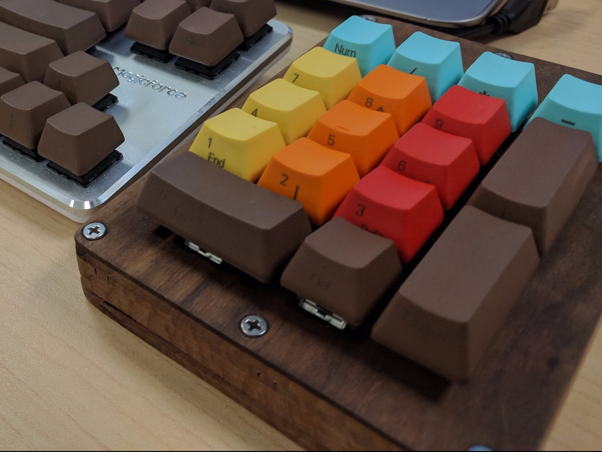
At this point we can put the keycaps on temporarily to check out the look and fit. Make sure to take them off until the end, so you don’t scratch them. Mine was looking great at this point, and I was very excited to finish the project.
Stabilizers
You might recall we set the stabilizers to Costar in the Python script to generate the CAD files. I attempted to install them but the BoardBuilder wound up making them a little too small. Since it was just a numpad, I didn’t mind there not being stabilizers, plus they were a pain to install in the first place. For a full sized keyboard we’ll definitely want to reconsider installing them.
Designing the Switch Circuit
It’s time to connect the switches, but first we need a plan. The basic idea of the circuit is to create rows and columns, so we can poll them in the firmware.


This shows the physical layout of the rows (Rx) and columns (Cx). You’ll notice that since we don’t have an exact 4×5 grid, some of the columns are missing rows. We will accommodate for this in the firmware. But first, we need to design our actual circuit.

Rows and Diodes
We need to add a diode to each switch, so they can be isolated from one another during polling. Make sure you have all of the diodes facing the same direction, or else you will have to resolder them. You should be able to notice the black ring at the end of the diodes which denotes their direction.
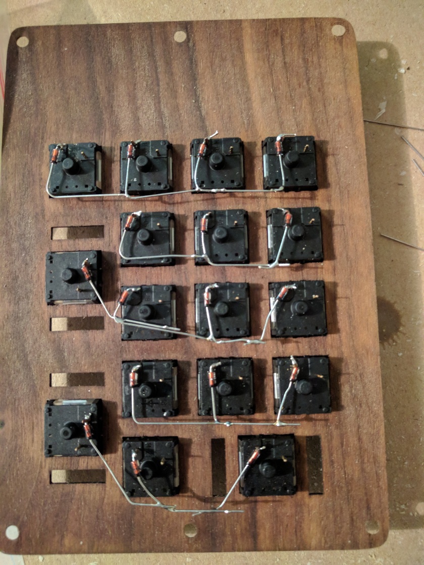
Columns
Now that we have our diodes, which also happen to make up the rows, we’ll need to wire the columns next. These are simply a strand of wire for each column. While we’re at it, we’ll also add a wire coming off each row so we can reach the microcontroller.

At this point I was not comfortable with how much flex my thin wooden faceplate had, so I added some balsa wood braces to help keep things strong. It probably was not 100% necessary but I’d rather be safe than sorry.
Connecting the Microcontroller
Now that the switches are wired, we need to figure out how to connect them to the IO pins on our microcontroller. This will depend on what hardware we decided to use, but I went for a Teensy 2.0. I used this pinout to determine how to come up with my final circuit.

Basically we have a group of column pins and a group of row pins. We’ll make sure to put this into the firmware later.
We now need to solder the rows and columns to the appropriate pins on the microcontroller. Make sure you double check the pinout and also make sure you give yourself enough wire to move the microcontroller around once you’re done.


In the pictures above you can see that the microcontroller is floating. I struggled to fit everything inside the case nicely so I wound up using a hot glue gun to attach the microcontroller to the faceplate. With the circuit completed and everything secured, we’re done with the hardware! All that’s left is to write the firmware and test it out.
